Solutions · Application Scenarios
Brine concentration: shrinking volume before disposal or thermal end-points
Concentration staging with LSI/silica governance and traceable brine chemistry. Smaller downstream duty and clearer solids handling narrative.
Use this guide within its scope
This page supports technical research and option comparison and is marked 2026. Illustrative values are not a quotation, completed process design, certification conclusion, or performance guarantee. Check current regulations, feed data, tests, and OEM records.
Problem
Disposal and thermal costs scale with volume—every m³ of avoided permeate loss matters.
Technology
Concentration staging with LSI/silica governance and traceable brine chemistry.
Results
Smaller downstream duty and clearer solids handling narrative.
Engineering decision card
Use when
Disposal and thermal costs scale with volume—every m³ of avoided permeate loss matters.
Evaluate first
Concentration staging with LSI/silica governance and traceable brine chemistry.
Inputs still required
Feed source and variability, capacity, target quality, operating hours, discharge or reuse boundary, available space, and utilities.
Comparison output
Smaller downstream duty and clearer solids handling narrative. The final decision still needs feed data, mass balance, and any necessary testing.
Process Context & When This Scenario Is the Right Entry Point
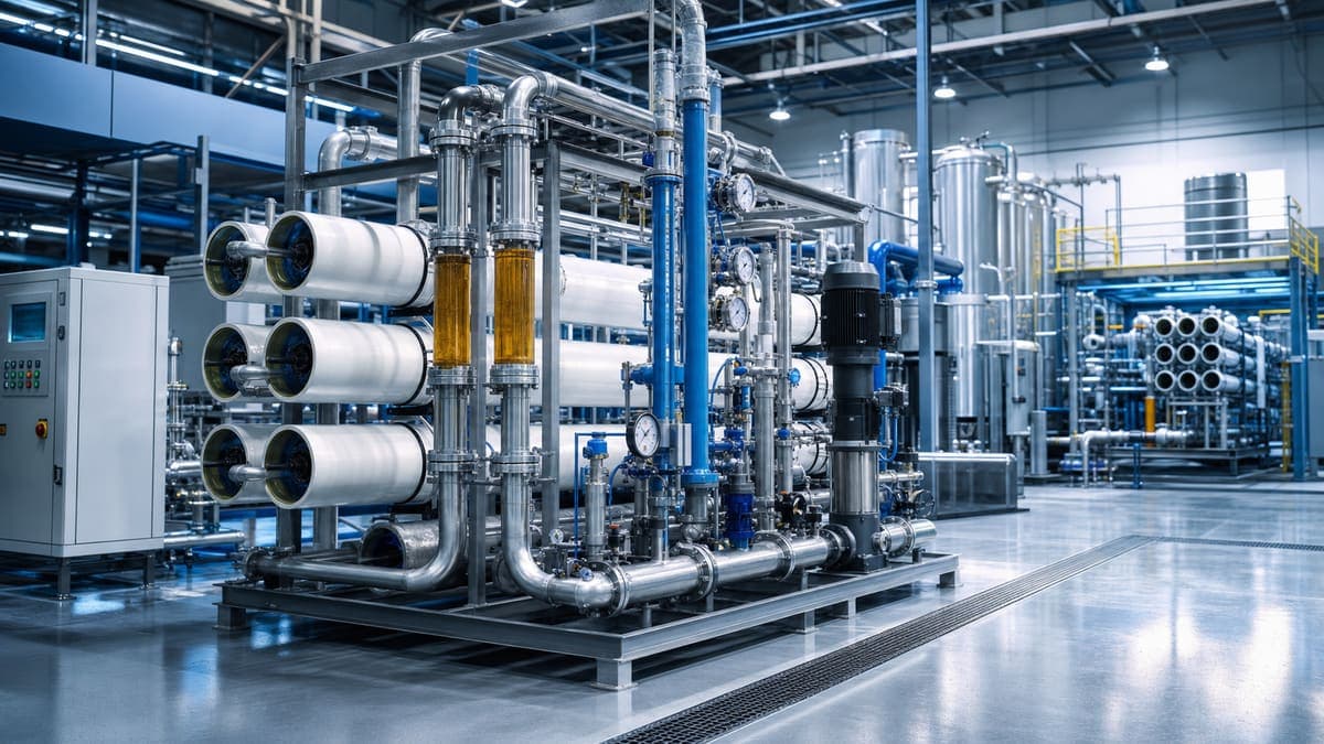
Brine concentration is a critical process task aimed at significantly reducing the volume of high total dissolved solids (TDS) wastewater, typically the concentrate or reject stream from upstream reverse osmosis (RO) or nanofiltration (NF) systems. This scenario becomes essential when direct discharge of the reject is either not permitted, cost-prohibitive due to volume-based disposal fees, or when the overall objective is Zero Liquid Discharge (ZLD). By extracting as much clean water as possible from the brine, the volume requiring subsequent thermal treatment (e.g., evaporators, crystallizers) or off-site disposal (e.g., deep well injection, haul-off) is drastically minimized, leading to substantial reductions in operational expenditure and environmental footprint. This approach is prevalent in industries like power generation, upstream oil & gas, mining, chemical processing, and various manufacturing sectors facing stringent water reuse and discharge regulations.
Feed Characteristics & Key Risks
The feed to a brine concentration system is inherently challenging. It is characterized by high TDS, often exceeding 50,000 mg/L and in some cases, pushing well over 100,000 mg/L. Key ionic species typically include elevated concentrations of calcium, magnesium, barium, strontium, silica, sulfate, carbonate/bicarbonate, sodium, and chloride.
The primary risks for membrane-based brine concentration are:
- Scaling: The high concentration of sparingly soluble salts (e.g., gypsum (CaSO₄·2H₂O), silica (SiO₂), barium sulfate (BaSO₄), strontium sulfate (SrSO₄), calcium carbonate (CaCO₃)) in the concentrate stream necessitates meticulous chemical management. Langelier Saturation Index (LSI) values will be significantly positive, and other specific ion scaling indices must be carefully managed.
- Fouling: Despite upstream treatment, residual colloidal matter, organics, and biological growth can still lead to membrane surface fouling, especially at high pressures and low fluxes.
- Osmotic Pressure: As the brine concentrates, its osmotic pressure increases dramatically. This directly opposes the applied hydraulic pressure, requiring very high operating pressures (1000 psi and above) to achieve permeate flow, thereby increasing energy consumption.
- Regulatory Drivers: Compliance with ZLD mandates or stringent discharge limits for specific contaminants often necessitates maximum water recovery, pushing membrane systems to their operational limits.
Concentrate / Reject Routing
The mass balance principle dictates that whatever dissolved and suspended solids are removed from the permeate must accumulate in the concentrate. In a multi-stage membrane brine concentration system, the final concentrate stream, now at its highest possible TDS, requires a defined disposition. The permeate (product water) from these systems is typically recycled back into the plant's process, used as boiler feedwater makeup, or reused for non-potable applications, significantly reducing raw water demand.
The concentrate stream from the final membrane stage is not discarded directly. Its routing options include:
- Further Thermal Treatment: The most common and economically favorable pathway for ZLD applications. The highly concentrated brine serves as feed to mechanical vapor recompression (MVR) evaporators, multi-effect evaporators (MEE), or crystallizers, where water is boiled off, and solids are recovered as a dry cake or slurry. This significantly reduces the energy footprint of the thermal system compared to feeding a dilute brine.
- Evaporation Ponds: If climatically suitable, geologically sound, and permitted by regulations, large evaporation ponds can be used for final brine disposal, though this is less common for new industrial facilities due to environmental concerns and land footprint.
- Deep Well Injection (DWI): In regions with appropriate geology and regulatory approval, the concentrated brine can be injected into deep, non-potable aquifers. Pre-filtration is often required to prevent well plugging.
- Haul-off to Licensed Disposal Facilities: For smaller volumes or when other options are not viable, the concentrated brine can be trucked to a specialized industrial wastewater treatment or disposal facility. This is typically the most expensive option per unit volume.
- Salt Recovery: In niche cases where valuable salts (e.g., lithium, sodium chloride) are present, the brine can be further processed for salt harvesting and purification.
The primary objective of membrane brine concentration is to minimize the volume directed to these endpoints, thus reducing capital and operating costs associated with downstream handling.
Reference Process Train Options
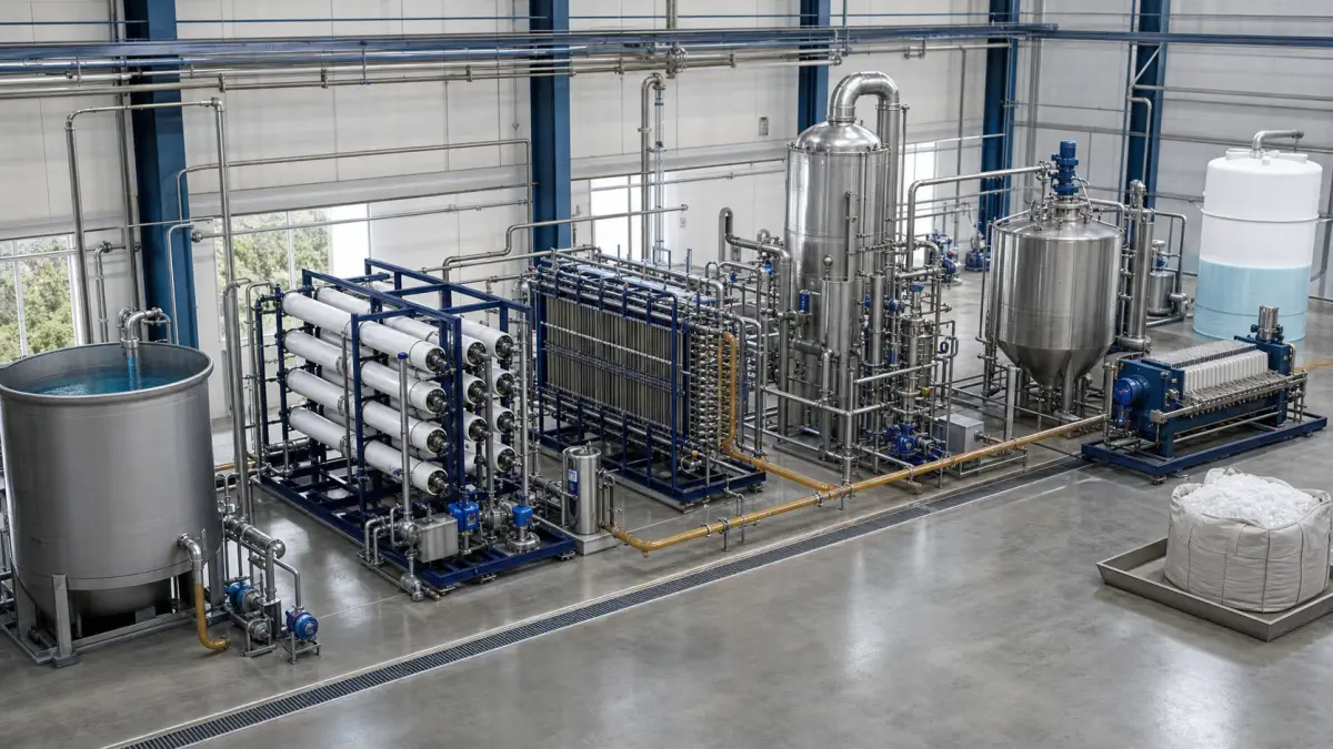
Effective brine concentration often involves a multi-pronged approach:
- Pretreatment: Robust pretreatment is non-negotiable. This typically includes chemical clarification, multi-media filtration, and often ultrafiltration (UF) or microfiltration (MF) to achieve stringent SDI targets. Chemical conditioning with coagulants, flocculants, pH adjustment (e.g., acid dosing to prevent carbonate scaling, caustic dosing for silica/metal hydroxide control), and multi-component antiscalant dosing are critical.
- Membrane Staging:
- Initial RO/NF: Depending on the feed TDS, a conventional RO system or a specialized NF membrane might be employed as a first stage to achieve initial volume reduction and remove specific ions. NF can selectively pass monovalent ions while rejecting multivalent ions, reducing the osmotic pressure burden on subsequent high-pressure RO stages.
- High-Pressure RO (HPRO): As TDS increases, standard RO systems are replaced by HPRO, operating at pressures typically between 800-1200 psi. These systems are designed to overcome the higher osmotic pressure of moderately concentrated brines.
- Ultra-High Pressure RO (UHPRO): For achieving maximum recovery and pushing the concentration limits, UHPRO systems operate at pressures up to 1800 psi or even higher in specialized designs. These systems are at the forefront of membrane brine concentration technology.
- Staged Membrane Arrays: Multiple stages of HPRO/UHPRO in series (e.g., three or four stages) with interstage pH adjustment and antiscalant redosing are common to maximize overall water recovery.
- Interstage Treatment: Between membrane stages, adjustments to pH and additional antiscalant dosing are often necessary to manage saturation indices as the brine becomes progressively concentrated. Degasification may also be required if CO₂ is generated from acid dosing.
- Integration with Thermal Systems: The concentrate from the final UHPRO stage is typically fed directly to an evaporator or crystallizer. This integrated approach ensures the most energy-efficient and cost-effective ZLD solution.
Operating Parameters
Precision in monitoring and control of operating parameters is paramount for sustainable brine concentration:
- SDI₁₅ (Silt Density Index): A critical indicator of colloidal fouling potential. For HPRO/UHPRO systems, the SDI₁₅ of the feed must consistently be maintained below 4, with targets often set at <3 or even <2 for high-recovery, difficult brines. Deviations from this target rapidly lead to fouling and irreversible membrane damage.
- LSI (Langelier Saturation Index) / Scaling Posture: While conventional RO aims for slightly negative LSI in the concentrate, brine concentrators often operate with the LSI and other specific scaling indices (e.g., CaSO₄, BaSO₄, SiO₂) slightly positive at the tail end of the membrane elements. This requires advanced antiscalant chemistry and precise pH control. Careful monitoring of saturation levels for key scaling species is essential to avoid precipitation.
- Flux (LMH): Due to the high osmotic pressure, high fouling/scaling potential, and the need for high rejection, membrane flux rates are conservative. Typical design fluxes for HPRO/UHPRO range from 8 to 15 L/(m²·h). Lower flux rates enhance membrane longevity and reduce fouling rates, albeit requiring more membrane surface area.
- DP (Differential Pressure): Monitoring the differential pressure (ΔP) across individual membrane vessels and across entire stages is crucial. A sustained increase in ΔP indicates fouling or scaling within the membrane elements. A rise of 10-15 psi above baseline for an individual vessel often triggers a Clean-In-Place (CIP) procedure. Overall stage ΔP in HPRO/UHPRO systems can be substantial, often 60-80 psi or higher from inlet to outlet.
Digital Twin & Instrumentation
The complexity and criticality of brine concentration systems make a robust digital twin and instrumentation platform indispensable.
Instrumentation: The system is instrumented with a dense array of sensors:
- Flow Meters: Monitoring feed, permeate, concentrate, and CIP flows.
- Pressure Transducers: High-accuracy sensors at feed inlet, interstage points, permeate outlets, concentrate outlets, and crucially, individual membrane vessel inlet/outlet to track ΔP.
- Conductivity Sensors: Real-time measurement of feed, permeate, and concentrate conductivity for precise salt rejection and concentration factor tracking.
- Temperature Sensors: Monitoring feed and CIP solution temperatures.
- pH Sensors: Essential for feed pretreatment, interstage chemistry adjustments, and CIP.
- Online Analyzers: For critical parameters like SDI, turbidity, ORP, and specific ions (e.g., silica, iron) in the pre-treatment effluent.
- Dosing Pump Feedback: Verification of antiscalant and acid/caustic dosing rates.
Pilot-Scale vs Industrial RO
For brine concentration applications, the choice between pilot-scale RO and industrial RO depends on scale and purpose. The pilot-scale RO is ideal for pilot-scale testing, temporary operations, or small-footprint brine concentration challenges, typically handling flows up to ~50 GPM permeate. It provides a flexible platform to validate membrane performance, optimize antiscalant chemistry, and determine sustainable recovery rates and operating fluxes for specific, novel, or highly variable brine streams without committing to significant capital investment. Its mobile nature is advantageous for site-to-site studies. In contrast, the industrial RO is engineered for production-scale, continuous brine concentration, processing hundreds to thousands of GPM permeate. These robust, multi-stage HPRO/UHPRO plants feature advanced pretreatment, integrated chemical dosing, full SCADA integration, and sophisticated mechanical designs, ensuring high recovery, energy efficiency, and long-term reliability for challenging ZLD and volume reduction objectives.
Common Engineering Mistakes & Pilot KPIs
Common Engineering Mistakes:
- Inadequate Feed Characterization: Underestimating variability in feed TDS, temperature, pH, or specific foulants (e.g., high organics, metals).
- Insufficient Pre-treatment Design: Failure to achieve and consistently maintain the required SDI₁₅, leading to rapid colloidal fouling and scaling.
- Overly Aggressive Recovery Targets: Pushing membrane recovery too high without proper chemical management, resulting in rapid scaling and irreversible membrane damage.
- Ignoring Interstage Chemistry: Neglecting to re-dose antiscalants or adjust pH between high-recovery stages where concentration factors dramatically increase.
- Suboptimal Antiscalant Selection: Using a general-purpose antiscalant for complex brine chemistries instead of one tailored to specific scaling species and pH ranges.
- Insufficient Concentrate Handling: Lack of properly designed concentrate tankage, transfer pumps, or integration with downstream thermal systems, leading to operational bottlenecks.
- Lack of Spares: Underestimating the need for critical spares for high-pressure pumps, energy recovery devices, and membrane elements, leading to extended downtime.
Key Pilot KPIs:
- Sustainable Permeate Recovery: Achievable percentage of water recovery without excessive fouling or scaling.
- Normalized Permeate Flux: Consistent permeate flow per unit of membrane area, indicating membrane health.
- Salt Rejection: Percentage of dissolved salts rejected, ensuring product water quality.
- Specific Antiscalant Dosage: Optimized chemical consumption per volume of feed.
- Membrane Cleaning Frequency & Effectiveness: How often CIP is required and how well it restores performance.
- Energy Consumption (kWh/m³ concentrated): Direct operating cost.
- ΔP Trends: Rate of pressure drop increase across elements/stages.
- Pilot Membrane Autopsy Results: Post-mortem analysis of membrane foulants and condition.
FAQ
Q: What's the practical limit for brine concentration with membranes? A: The practical limit is primarily dictated by the osmotic pressure of the brine, the maximum operating pressure of the membranes and pumps, and the solubility limits of sparingly soluble salts. With UHPRO technology, brines can be concentrated up to 120,000-150,000 mg/L TDS, and in some specialized cases, even higher, before reaching the physical limits of membrane performance or the onset of severe scaling.
Q: How do you handle silica scaling at high recoveries? A: Silica scaling is challenging because its solubility is pH-dependent. Strategies include operating at an optimal pH (often slightly alkaline where silica is more soluble but metal hydroxides might precipitate, requiring careful balance), using specialized antiscalants designed for silica, and in some cases, incorporating silica removal pre-treatment (e.g., warm lime softening or adsorption processes) before the membrane stages.
Q: Is NF always beneficial before HPRO? A: Not always, but often. NF can be beneficial when the feed brine contains high concentrations of multivalent ions (like Ca²⁺, Mg²⁺, SO₄²⁻) that contribute significantly to scaling and osmotic pressure, but also monovalent ions (Na⁺, Cl⁻) that are less problematic. NF can selectively reject the multivalent ions while passing a portion of the monovalent ions, reducing the osmotic pressure on subsequent HPRO stages and potentially improving overall recovery and reducing HPRO operating pressures.
Q: What is the typical energy consumption for HPRO/UHPRO? A: Energy consumption for HPRO/UHPRO is significant due to the high operating pressures. While specific figures vary widely with feed TDS, recovery, and system design, it can range from 8-15 kWh/m³ of permeate produced, and even higher for extremely concentrated brines. The use of energy recovery devices (ERDs) is standard practice to recover energy from the high-pressure concentrate stream, significantly reducing net energy consumption.
Related equipment & product lines
These categories typically support the approach above—open any line to compare brands and models.
For a closer review, use the engineering inquiry form to share feed, capacity, target, and project stage. Submission does not constitute a completed design or performance commitment.