Solutions · Application Scenarios
Oil–water separation for produced water and emulsions
Graduated separation with explicit oily waste and reject pathways. Water phase suitable for reuse or discharge with documented oil-bearing residuals.
Use this guide within its scope
This page supports technical research and option comparison and is marked 2026. Illustrative values are not a quotation, completed process design, certification conclusion, or performance guarantee. Check current regulations, feed data, tests, and OEM records.
Problem
Emulsified oil fools sensors and blinds pretreatment—membrane risk follows.
Technology
Graduated separation with explicit oily waste and reject pathways.
Results
Water phase suitable for reuse or discharge with documented oil-bearing residuals.
Engineering decision card
Use when
Emulsified oil fools sensors and blinds pretreatment—membrane risk follows.
Evaluate first
Graduated separation with explicit oily waste and reject pathways.
Inputs still required
Feed source and variability, capacity, target quality, operating hours, discharge or reuse boundary, available space, and utilities.
Comparison output
Water phase suitable for reuse or discharge with documented oil-bearing residuals. The final decision still needs feed data, mass balance, and any necessary testing.
1. Process context & when this scenario is the right entry point
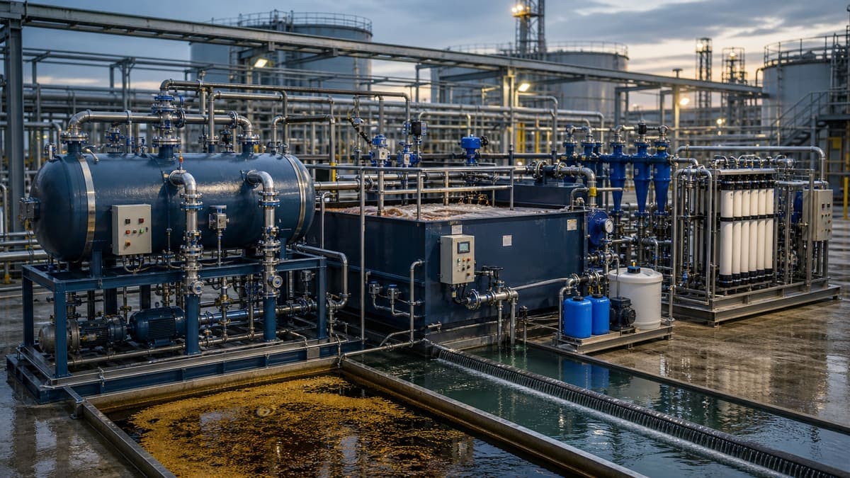
This scenario addresses the critical need for efficient oil and water separation in industrial process streams, particularly in oil and gas production (produced water), refining, petrochemicals, and various manufacturing facilities generating oily wastewater. The primary objective is to recover clean water for discharge, reuse, or further treatment, while concentrating the oil and suspended solids for disposal or recovery. This scenario is the appropriate entry point when the feed stream contains significant quantities of free, dispersed, or emulsified oils alongside suspended solids and dissolved salts, where traditional gravity separation is insufficient to meet discharge or downstream process specifications. Effective separation is paramount for environmental compliance, resource recovery, and protecting sensitive downstream equipment such as heat exchangers, boilers, and membrane systems.
2. Feed characteristics & key risks
Produced water and oily emulsions present a complex matrix of contaminants. Typical feed characteristics include:
- Oil & Grease (O&G): Ranging from 50 mg/L to several thousand mg/L, often present as stable emulsions that are difficult to break.
- Total Suspended Solids (TSS): Variable, from <100 mg/L to >1000 mg/L, including silt, clays, corrosion products, and biological solids.
- Total Dissolved Solids (TDS): Highly variable, from brackish (a few thousand mg/L) to hypersaline (over 100,000 mg/L), introducing osmotic challenges and scaling risks.
- Organic compounds: Naturally occurring organic matter, production chemicals (e.g., corrosion inhibitors, scale inhibitors, biocides), and dissolved hydrocarbons (e.g., BTEX).
- Hardness and Alkalinity: Contributes to scale formation.
Key risks during treatment include:
- Membrane fouling: Irreversible fouling by O&G, colloidal particles, and organic matter is the foremost challenge, leading to flux decline and increased cleaning frequency.
- Scaling: High concentrations of sparingly soluble salts (e.g., calcium carbonate, calcium sulfate, barium sulfate, silica) can precipitate on membrane surfaces, especially at high recovery rates. The LSI can exceed +2.0 in some produced waters, indicating a high scaling propensity.
- High osmotic pressure: For high TDS feeds, particularly with RO, the osmotic pressure can be significant, requiring very high operating pressures and limiting water recovery.
- Regulatory compliance: Stringent discharge limits for O&G (e.g., <5-10 mg/L), TSS, and other pollutants demand robust treatment.
3. Concentrate / reject routing
A comprehensive mass balance approach dictates that all concentrate and reject streams must have a defined disposition.
- Primary/Secondary Separation Sludges: Sludge generated from API separators, DAF, or IGF units (containing concentrated oil, TSS, and entrained water) is typically dewatered using filter presses or centrifuges. The resulting filter cake or solids are then disposed of in an approved industrial landfill or incinerated. The separated water is usually recycled back to the upstream treatment or discharged if meeting specifications.
- Media Filter Backwash: Backwash water from multi-media filters contains accumulated TSS and some oil. This stream is often sent to a clarifier for solids settling, with the clarified supernatant recycled to the head of the plant or discharged. The settled sludge is managed similarly to primary sludges.
- Membrane Reject (UF/NF/RO): The concentrate from UF, NF, or RO stages will contain a significantly higher concentration of all contaminants present in the feed, including residual O&G, TSS, and particularly TDS.
- Deep well injection: A common practice in the oil and gas industry, where the reject is injected into suitable geological formations. This requires specific geological assessments and regulatory permits.
- Further concentration/ZLD: For sites aiming for Zero Liquid Discharge (ZLD), the membrane reject is sent to thermal evaporators or crystallizers to recover additional water and produce a solid waste (salt cake) for disposal.
- Haul-off: For smaller volumes, the reject may be trucked off-site to a specialized wastewater treatment facility or disposal well.
- Return to process: In some refinery or petrochemical applications, if the quality is compatible, a portion of the reject may be recycled back to an upstream process like a crude desalter, managing salinity and oil content carefully. This requires stringent monitoring to prevent system upsets.
4. Reference process train options
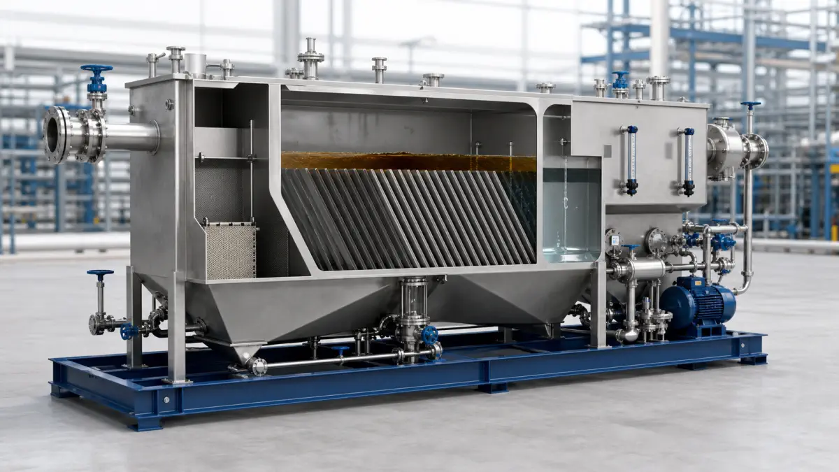
Effective oil-water separation often requires a multi-stage process train, balancing capital and operating expenditures with performance requirements.
- Primary Separation: For gross O&G removal.
- API Separator / Corrugated Plate Interceptor (CPI): Gravity-based separation for free oil and large suspended solids (O&G > 100 mg/L).
- Secondary Separation: Reducing O&G and TSS further.
- Dissolved Air Flotation (DAF) / Induced Gas Flotation (IGF): Enhances separation of fine oil droplets and suspended solids by introducing micro-bubbles. Often coupled with chemical pre-treatment (coagulants like ferric chloride or aluminum sulfate, and flocculants) to destabilize emulsions and aggregate particles. This step typically targets O&G < 5-20 mg/L.
- Coalescing plate separators: Uses oleophilic plates to encourage oil droplet coalescence.
- Tertiary Polishing & Membrane Pre-treatment: Critical for protecting downstream membranes.
- Multi-media filtration: Removes residual suspended solids.
- Activated Carbon Filtration: Adsorbs dissolved organics and residual oils.
- Ultrafiltration (UF) / Microfiltration (MF): Provides a robust barrier for TSS, colloidal particles, and emulsified oil, ensuring a stable feed for NF/RO with an SDI₁₅ typically < 3-5. UF is highly effective in breaking stable emulsions through mechanical separation.
- Advanced Separation (Membrane Filtration):
- Nanofiltration (NF): Used for selective removal of divalent ions (hardness) and some organics, while allowing monovalent salts to pass, reducing the osmotic pressure challenge for subsequent RO.
- Reverse Osmosis (RO): For high-purity water requirements, capable of removing up to 99%+ of TDS and trace organics. Anti-scalants are commonly dosed upstream to mitigate scaling risk, especially where LSI is high or silica concentrations are significant.
- Post-Treatment (if required):
- Electrodeionization (EDI): For continuous production of ultrapure water (e.g., boiler feed, process make-up) from RO permeate, eliminating the need for chemical regeneration.
- Degasification: For CO2 removal to reduce permeate conductivity and protect downstream ion exchange resins.
5. Operating parameters
Precise control and monitoring of key operating parameters are essential for sustained performance and asset integrity.
- SDI₁₅ (Silt Density Index): A critical parameter for membrane feed water quality. For RO membranes, a target SDI₁₅ of < 3-5 is mandatory to prevent colloidal fouling. UF/MF permeate typically achieves this consistently.
- LSI (Langelier Saturation Index): While specific to calcium carbonate, the concept of saturation indices is vital. Water chemistry models are used to calculate saturation for various scaling species (CaCO₃, CaSO₄, BaSO₄, SrSO₄, SiO₂). Anti-scalant dosing strategies are developed to maintain a sub-saturated or slightly super-saturated state (e.g., LSI < +2.0 without causing precipitation) in the concentrate stream at the design recovery.
- Flux (LMH): Design flux (L/(m²·h)) for UF typically ranges from 30-80 LMH, while for NF and RO, it's generally lower, from 8-20 LMH, depending heavily on feed quality, temperature, and membrane type. Higher fluxes increase production but also accelerate fouling and scaling. Consistent flux is a primary KPI for membrane health.
- Differential Pressure (ΔP): Monitoring the ΔP across individual membrane elements or stages is crucial. A sustained increase in ΔP (e.g., >10-15% over baseline or typical stage ΔP > 0.7-1.0 bar / 10-15 psi) indicates fouling or plugging and signals the need for a Clean-In-Place (CIP) cycle or backwash. Similarly, pre-filter ΔP indicates loading and dictates cartridge replacement or media filter backwash frequency.
7. Pilot-Scale vs Industrial RO
For oil-water separation applications, the choice between pilot-scale RO and industrial RO depends on scale, complexity, and project phase. pilot-scale RO units are ideal for pilot-scale testing, temporary installations, or treating smaller volumes of produced water (e.g., <100 m³/day) where flexibility and rapid deployment are key. They allow for critical on-site validation of pre-treatment efficacy, membrane performance (flux, recovery, fouling rates), and chemical optimization specific to a unique oily wastewater. For robust, continuous, large-scale operations requiring high uptime and intricate integration, industrial RO systems are specified. These are engineered for multi-stage membrane trains, often incorporating advanced pre-treatment and ZLD-class components, with full SCADA integration into existing plant control systems, treating thousands of cubic meters per day with optimized energy efficiency and full automation.
8. Common engineering mistakes & pilot KPIs
Common Engineering Mistakes:
- Underestimating emulsion stability: Assuming free oil separation is sufficient, leading to rapid downstream membrane fouling by stable emulsions. Often requires dedicated chemical demulsifiers or robust UF pre-treatment.
- Insufficient pre-treatment: The leading cause of membrane failure in produced water applications. Failing to achieve consistent low SDI₁₅ (<3-5) and O&G (<1-3 mg/L) in the membrane feed.
- Inadequate concentrate management: Neglecting to fully define the disposition and cost of all reject streams (sludges, membrane reject), leading to unexpected operational bottlenecks and costs.
- Ignoring dissolved gases: Dissolved H₂S, CO₂, and light hydrocarbons can cause gas lock in membranes or corrosion.
- Poor chemical selection/dosing: Incorrect anti-scalants or coagulants can exacerbate fouling or scale, or be ineffective.
Pilot Key Performance Indicators (KPIs):
- Permeate quality: Consistent O&G (<1-3 mg/L), TSS (<1 mg/L), SDI₁₅ (<3), TDS reduction.
- Stable flux: Demonstrating sustained design flux over extended periods with acceptable ΔP increases.
- Water recovery: Achievable water recovery rate without excessive fouling or scaling.
- Chemical consumption: Actual usage rates of coagulants, flocculants, anti-scalants, and cleaning chemicals.
- Energy consumption: Specific energy demand (kWh/m³ product water).
- Cleaning frequency: Documented CIP frequency and effectiveness, indicating membrane resilience.
9. FAQ
Q1: How do I deal with highly stable oil-in-water emulsions? A: Stable emulsions often require a combination of chemical and physical methods. Chemical demulsifiers destabilize the oil droplets, followed by enhanced separation techniques like DAF, IGF, or high-shear mixing with subsequent coalescence. Ultrafiltration (UF) membranes are also highly effective at physically rejecting emulsified oils.
Q2: What are the main challenges for Reverse Osmosis in produced water treatment? A: The primary challenges are severe fouling from residual oils, organics, and suspended solids; scaling from high concentrations of sparingly soluble salts (e.g., calcium sulfate, silica); and high osmotic pressure requiring elevated operating pressures and limiting recovery, especially in hypersaline feeds.
Q3: Can I reuse the treated produced water? A: Yes, with proper treatment, the permeate can be reused for various industrial applications such as cooling tower make-up, boiler feed water (often requiring further polishing like EDI), or non-potable process water. The level of treatment required depends on the specific reuse application and its water quality specifications.
Q4: What if I have high silica concentrations in my produced water? A: High silica can lead to significant scaling. Strategies include pH adjustment to keep silica soluble, specialized silica anti-scalants, or upstream hot lime softening which effectively removes silica, calcium, and magnesium. Operating at lower recovery rates for the final membrane stage can also mitigate silica saturation.
Related equipment & product lines
These categories typically support the approach above—open any line to compare brands and models.
- Filtration MediaGranular and specialty media for depth filtration and polishing stages.View category →
- RO MembranesReverse osmosis membrane elements for municipal and industrial desalination.View category →
- Pilot Units TestingPilot rigs and trial modules for process validation and feasibility studies.View category →
For a closer review, use the engineering inquiry form to share feed, capacity, target, and project stage. Submission does not constitute a completed design or performance commitment.