Solutions · Industry Solutions
Semiconductor ultrapure water (UPW): approaching 18.2 MΩ·cm
How fabs specify UPW for advanced nodes: resistivity, trace metals, TOC, and polishing—RO, EDI, UV, and evidence-based acceptance testing.
Use this guide within its scope
This page supports technical research and option comparison and is marked 2026. Illustrative values are not a quotation, completed process design, certification conclusion, or performance guarantee. Check current regulations, feed data, tests, and OEM records.
Problem
Yield-critical fabs need more than online resistivity: trace metals, boron, silica, and TOC excursions can pass alarms yet still damage wafers.
Technology
Layered barriers—pretreatment, single- or double-pass RO, continuous EDI or mixed-bed polishing, and targeted UV/TOC steps sized to real organics.
Results
Stable quality against seasonal raw-water shifts, with contracts tied to analytes and methods that actually matter for the process node.
Engineering decision card
Use when
Yield-critical fabs need more than online resistivity: trace metals, boron, silica, and TOC excursions can pass alarms yet still damage wafers.
Evaluate first
Layered barriers—pretreatment, single- or double-pass RO, continuous EDI or mixed-bed polishing, and targeted UV/TOC steps sized to real organics.
Inputs still required
Feed source and variability, capacity, target quality, operating hours, discharge or reuse boundary, available space, and utilities.
Comparison output
Stable quality against seasonal raw-water shifts, with contracts tied to analytes and methods that actually matter for the process node. The final decision still needs feed data, mass balance, and any necessary testing.

Industry Context & Regulatory/Compliance Drivers
The demand for ever-increasing purity in semiconductor UPW is driven by the relentless pursuit of smaller, more powerful, and reliable microchips. Advanced nodes require the removal of contaminants to levels often below detection limits of conventional instrumentation. Key drivers include:
- Yield Improvement: Particles, ionic impurities (e.g., sodium, calcium, transition metals, boron), silica, and Total Organic Carbon (TOC) can cause defects, reducing chip yield and increasing manufacturing costs.
- Process Stability: Consistent UPW quality ensures stable chemical reactions and cleaning processes.
- Material Compatibility: Preventing contamination that could react with or degrade sensitive materials used in device fabrication.
- Global Standards: While not strictly regulatory in the same way as drinking water, industry standards such as ASTM D5127-13 (Standard Guide for Ultrapure Water Used in the Electronics and Semiconductor Industries) provide critical guidance on achievable water quality for various applications (e.g., Type E-1.2 for advanced processes). Local environmental regulations also dictate the discharge quality of spent process water and RO concentrate.
Water Quality Targets for Advanced Semiconductor Manufacturing
For an advanced semiconductor facility targeting Type E-1.2 quality under ASTM D5127-13, the UPW specification matrix often includes:
- Resistivity: >18.2 MΩ·cm at 25 °C (typically measured as the "resistivity target").
- Total Organic Carbon (TOC): <1.0 µg/L (ppb), often <0.5 µg/L.
- Particles: <10 particles/mL at >0.1 µm, with even tighter limits for smaller particle sizes.
- Dissolved Gases (O₂, CO₂): Often below 10 µg/L (ppb) each, requiring membrane degasification.
- Bacteria: <1 CFU/100 mL (Colony Forming Units), often <1 CFU/1000 mL.
- Ionic Impurities (e.g., Na⁺, K⁺, Ca²⁺, Fe, Cu, Zn, Cl⁻, SO₄²⁻, SiO₂): Individual ion concentrations typically <10 ng/L (ppt), often <1 ng/L. Boron is a critical impurity requiring specialized removal.
The raw water source for a fab, whether municipal tap water or surface water, presents its own unique challenges, including seasonal variations in turbidity, organics, and dissolved solids. These variations necessitate a robust, multi-barrier treatment approach.
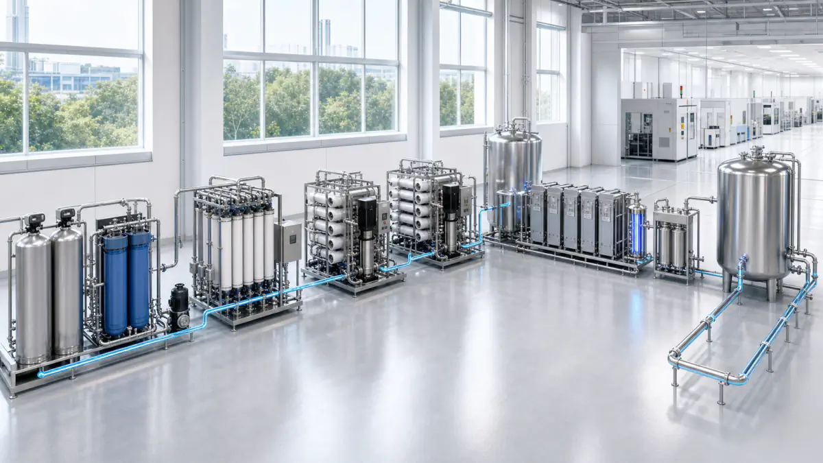
1. Pretreatment – Safeguarding the Core System
Effective pretreatment is paramount for protecting downstream membrane and ion exchange systems from fouling and premature degradation. For challenging surface water or municipal feeds with an SDI₁₅ above 5, multimedia filtration (MMF) followed by ultrafiltration (UF) is explicitly required to manage suspended solids and turbidity.
- Coagulation/Flocculation & MMF: For high turbidity waters, a clarification step may precede MMF to remove larger suspended solids.
- Ultrafiltration (UF): Provides a superior physical barrier against suspended solids, colloids, bacteria, and viruses, significantly reducing the SDI of the feed water. This is crucial for protecting the sensitive RO membranes.
- Activated Carbon Filtration: Removes free chlorine, chloramines, and larger organic molecules that can foul RO membranes or contribute to TOC.
- Chemical Dosing: Includes antiscalants to prevent scaling on RO membranes, bisulfite for chlorine/chloramine reduction, and pH adjustment where necessary.
- Softening (optional): For very hard raw water, an ion exchange softener might be used upstream of RO to remove hardness ions (Ca, Mg) and reduce scaling potential.
2. Primary Demineralization – The Reverse Osmosis Core
Reverse Osmosis (RO) is the workhorse of demineralization, removing up to 99% of dissolved inorganic salts, particles, and larger organic molecules.
- RO Pressure Vessel Train: The core of the demineralization system. We analyze feed water chemistry to optimize membrane selection and operating parameters such as flux (L/(m²·h)), cross-flow, and recovery rate. High recovery rates require careful management of concentration polarization and LSI (Langelier Saturation Index) to mitigate scaling risks (e.g., calcium carbonate, silica).
- Double-Pass RO: Often employed in semiconductor applications to achieve higher rejection of monovalent ions, silica, and critically, boron, which is poorly rejected by single-pass RO. The permeate from the first pass becomes the feed for the second pass, significantly reducing overall dissolved solids.
- Degasification (Membrane Contactor): Placed after the first-pass RO or between RO passes, this unit efficiently removes dissolved carbon dioxide, oxygen, and other non-condensable gases, which can reduce the load on downstream EDI/IX and improve the final resistivity.
3. Polishing – Achieving Ultrapure Standards
Following RO, further polishing is necessary to reach the stringent UPW specifications.
- Continuous Electrodeionization (EDI): this approach predominantly specifies EDI for its continuous, chemical-free operation. EDI stacks utilize a DC electric field, ion-exchange resin, and ion-selective membranes to continuously remove residual ions from the RO permeate. Ions migrate through the resin to concentrate channels and then through anion/cation-selective membranes into a concentrate compartment. Simultaneously, water splitting at the electrode membranes generates H+ and OH- ions that continuously regenerate the resin within the dilute compartment. A small portion of flow goes to the electrode compartments for ion removal and system flushing. This eliminates the need for hazardous acid/caustic regenerants used in conventional ion exchange.
- Mixed-Bed Ion Exchange (MBIX): For extremely tight specifications or specific contaminant removal, conventional mixed-bed ion exchange polishers may be used, offering superior polishing capabilities for very low ionic loads. However, they require off-line chemical regeneration.
4. Post-Treatment & Distribution – Maintaining Purity
The final stages focus on removing last traces of contaminants and preventing re-contamination.
- Ultraviolet (UV) Sterilization & TOC Reduction: Dual-wavelength UV reactors (e.g., 185 nm for TOC oxidation and 254 nm for sterilization) are crucial for destroying residual organic molecules and inactivating microorganisms.
- Final Submicron Filtration: Point-of-use filters with absolute ratings down to 0.05 µm or even smaller are employed to remove any remaining particles, typically located just before the point of use in the fab.
- Distribution Loop Design: The UPW loop is designed with smooth internal surfaces (e.g., PVDF, electropolished stainless steel), minimal dead legs, and controlled velocity to prevent microbial growth and particle shedding. Recirculation flow rates are optimized to ensure continuous refreshment of the water.
Operations, Monitoring, and CIP Philosophy
this approach's philosophy centers on predictive maintenance and proactive intervention, driven by continuous digital monitoring.
Risks and Common Engineering Mistakes
- Inadequate Pretreatment: Undersizing pretreatment for peak raw water events or neglecting SDI management leads directly to rapid RO membrane fouling and increased operational costs.
- Ignoring Concentration Polarization: In high recovery RO, failure to manage concentration polarization at the membrane surface can lead to localized supersaturation and severe scaling.
- Mismatch of Online vs. Lab Analytics: Acceptance criteria often rely on sophisticated lab analysis. A common mistake is to not correlate online sensor data with lab data effectively, leading to disputes during commissioning.
- Poor Loop Design: Dead legs, inappropriate materials, or insufficient sanitization in the distribution loop can lead to re-contamination, rendering the entire purification effort futile.
- Over-reliance on Resistivity: While 18.2 MΩ·cm is the reference, it is not a sufficient metric. Boron, silica, TOC, and particle counts are equally, if not more, critical for modern semiconductor processes.
engineering evaluation path Engineering Tip
Freeze two sampling programs in the specification: startup acceptance and worst-season operations. If polishing resin or EDI capacity is validated only on "kind" feed water, the first drought or algae event becomes an emergency resin change – not a forecastable opex line. This ensures resilience and continuous compliance regardless of raw water variability.
Related equipment & product lines
These categories typically support the approach above—open any line to compare brands and models.
- RO MembranesReverse osmosis membrane elements for municipal and industrial desalination.View category →
- Electrodeionization (EDI)EDI modules and systems for ultrapure water production.View category →
- Ion Exchange ResinsCation/anion and mixed bed resin solutions for demineralization and polishing.View category →
- UV DisinfectionUV systems and modules for pathogen inactivation and final disinfection barriers.View category →
For a closer review, use the engineering inquiry form to share feed, capacity, target, and project stage. Submission does not constitute a completed design or performance commitment.